[et_pb_section fb_built=”1″ theme_builder_area=”post_content” _builder_version=”4.27.4″ _module_preset=”default”][et_pb_row _builder_version=”4.18.0″ _module_preset=”default” width=”100%” custom_margin=”|||0px|false|false” global_colors_info=”{}” theme_builder_area=”post_content”][et_pb_column type=”4_4″ _builder_version=”4.18.0″ _module_preset=”default” global_colors_info=”{}” theme_builder_area=”post_content”][et_pb_code _builder_version=”4.27.4″ _module_preset=”default” global_colors_info=”{}” theme_builder_area=”post_content”]
What You Need:
Steps:
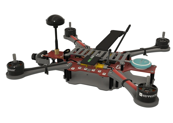
WARNING! Remove props and attach the antenna before connecting the battery.
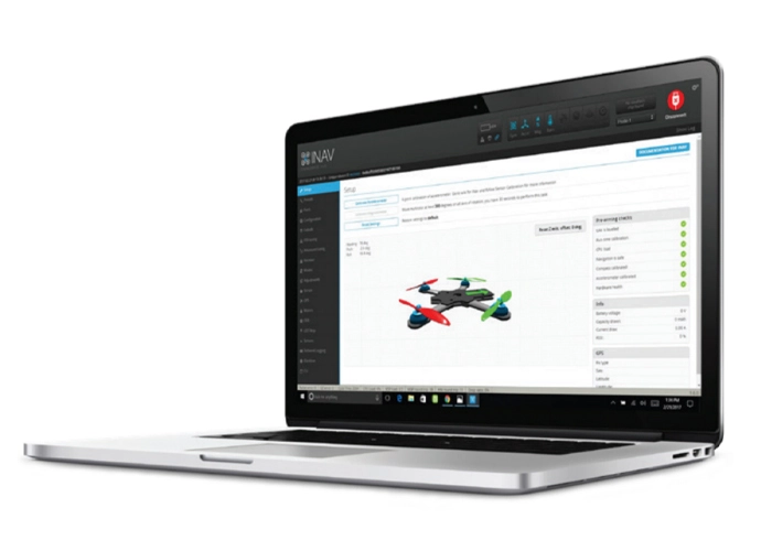
Connect RubiQ to INAV and scroll down to the LED Strip tab.[/et_pb_text][et_pb_image src=”https://staging.resources.edventures.com/wp-content/uploads/2025/06/LED-Tab-1.9.3.webp” title_text=”LED-Tab-1.9.3″ show_in_lightbox=”on” _builder_version=”4.27.4″ _module_preset=”default” global_colors_info=”{}” theme_builder_area=”post_content”][/et_pb_image][et_pb_text _builder_version=”4.27.4″ _module_preset=”default” width=”100%” global_colors_info=”{}” theme_builder_area=”post_content”]The LED ordering comes preconfigured to match the placement of the LED’s on the drone. The middle strips show the top of the PDB and the two outer arches show the LED’s on the bottom, with left corresponding to left and right to right when the drone is facing away from you.
In INAV, click on any LED to see what function it’s been programmed to perform.[/et_pb_text][et_pb_image src=”https://staging.resources.edventures.com/wp-content/uploads/2025/06/LED-Diagram-2.0.webp” title_text=”LED-Diagram-2.0″ show_in_lightbox=”on” _builder_version=”4.27.4″ _module_preset=”default” global_colors_info=”{}” theme_builder_area=”post_content”][/et_pb_image][et_pb_text _builder_version=”4.27.4″ _module_preset=”default” width=”100%” global_colors_info=”{}” theme_builder_area=”post_content”]
Functions:
GPS:
- The corner LEDs (0, 5, 6, 11, 12, 17, 18 and 23) show as dark green in INAV, indicating that they’re set to show GPS Function.
- Red light signals No Satellites (which you’ll probably see anytime you’re inside).
- Orange signals that Satellites Are Detected but not locked.
- Green shows that a GPS Connection is established. The number of green flashes communicates the number of connected satellites.
Note: since GPS lock is enabled, the drone won’t arm without a GPS connection.[/et_pb_text][et_pb_image src=”https://staging.resources.edventures.com/wp-content/uploads/2025/06/LED-Diagram-GPS-2.0.webp” title_text=”LED-Diagram-GPS-2.0″ show_in_lightbox=”on” _builder_version=”4.27.4″ _module_preset=”default” global_colors_info=”{}” theme_builder_area=”post_content”][/et_pb_image][et_pb_text _builder_version=”4.27.4″ _module_preset=”default” width=”100%” global_colors_info=”{}” theme_builder_area=”post_content”]
Arm State:
- The LEDs just inside the GPS Indicator lights (1, 4, 7, 10, 13, 16, 19 and 22) are solid blue in INAV, meaning their function is set to Arm State.
- When the drone is armed, these lights turn blue.
- Green lights indicate that the drone is disarmed.
[/et_pb_text][et_pb_image src=”https://staging.resources.edventures.com/wp-content/uploads/2025/06/LED-Diagram-Arm-State-2.0.webp” title_text=”LED-Diagram-Arm-State-2.0″ show_in_lightbox=”on” _builder_version=”4.27.4″ _module_preset=”default” global_colors_info=”{}” theme_builder_area=”post_content”][/et_pb_image][et_pb_text _builder_version=”4.27.4″ _module_preset=”default” width=”100%” global_colors_info=”{}” theme_builder_area=”post_content”]
Color:
- The inner LEDs (2, 3, 8, 9, 14, 15, 20 and 21) show up in INAV as lime green with a rainbow color border. This indicates that the function is set to show the color green.
Overlays:
Warning:
- The tiny red dot in the upper left corner of the inner LED’s (2, 3, 8, 9, 14, 15, 20 and 21) signals that the Warning Overlay is turned on.
- With this overlay active, a green flash indicates that Arm-lock is enabled, meaning that the drone will not arm until it has established a GPS-lock (this is enabled by default).
- Flashing red means the Battery is Low (3.7V is the default warning cell voltage setting).
- A blue flash means at least one Critical Hardware Malfunction, meaning a component is not working properly.
- If you see light-blue and yellow, you need to Enable Failsafe. To do this, open the Failsafe tab and make sure Failsafe Stage 2 enabled is activated.
[/et_pb_text][et_pb_image src=”https://staging.resources.edventures.com/wp-content/uploads/2025/06/LED-Diagram-Warning-2.0.webp” title_text=”LED-Diagram-Warning-2.0″ show_in_lightbox=”on” _builder_version=”4.27.4″ _module_preset=”default” global_colors_info=”{}” theme_builder_area=”post_content”][/et_pb_image][et_pb_text admin_label=”Troubleshooting” _builder_version=”4.27.4″ _module_preset=”default” global_colors_info=”{}” theme_builder_area=”post_content”]
Troubleshooting:
IIf you don’t see an array of LED’s matching those pictured in the instructions, you need to reset RubiQ back to her default settings from the Reset Default Configuration step.[/et_pb_text][/et_pb_column][/et_pb_row][/et_pb_section]